Input Parameters
Input parameters page specify the properties of the beam, soil, load cases and prescribed values. These are entered in their respective tabs.
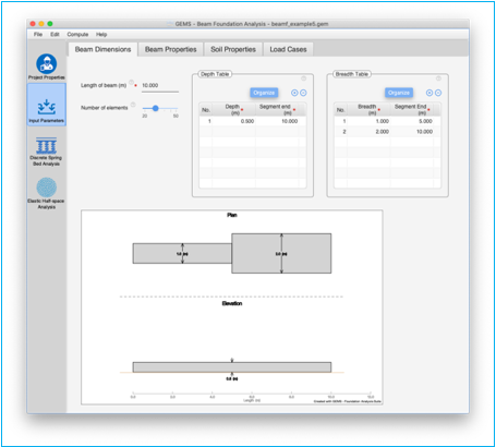
Beam Dimensions Tab
Beam dimensions tab defines the dimensions of the beam foundation.
Length of beam
Specify the length of the beam used in foundation here in the units specified. This should be one of the first items to be entered on this page.
![]()
Number of elements
This is the minimum number of elements used in the finite element calculation. The program may adjust this number incase this is not sufficient to carry out the analysis. A higher number of elements will improve granularity but may result in some loss of fidelity. The default value of 20 elements is recommended.
![]()
Use the slider to select the number of elements. A minimum of 20 elements and a maximum of 50 elements are supported
Breadth of beam
Specify the breadth of the beam used in foundation here in the units specified. When analysis using 'Elastic Half-space' method is selected in the project properties pane, this field is displayed and should be used.
![]()
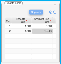
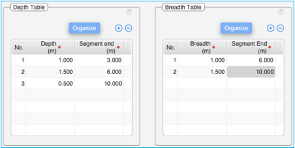
Breadth Table
The breadth table is used to define the breadth of the beam. When analysis using only 'Discrete spring bed' method is selected in the project properties pane, this table is displayed and should be used. Up 10 distinct breadth segments can be entered.
Use the (+) and (-) buttons at the top of the table to add / delete rows to the Breadth table.
[Organize] button can be used to sort the values in ascending order of 'Segment end' and to clean up empty entries in the table.
Table:
Double-click on the table cells to edit the content of the cells.
The table consists of three columns – 1) No., 2) Breadth and 3) Segment End. The 'No.' column cannot be edited.
To enter the breadth value, double click on the cell in this column and enter the value of breadth for each segment. The breadth values are restricted to the length of the beam.
Segment end Column – This defines the end value of each segment. For the first segment the beginning value is automatically assigned as zero. For all other segment the beginning values is automatically assigned the value corresponding to the end of the previous segment. For the last segment it is mandatory to assign a value equal to the length of the beam.
Right click on the table to bring-up the context menu to insert / delete rows in the table, cut, copy, delete and paste contents into the table. It is also possible to copy the table from excel and paste the contents into this table. Ensure adequate number of empty rows are added to the table prior to pasting contents from an excel table.
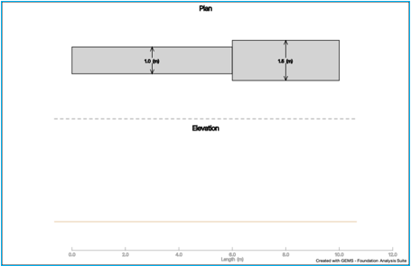
The plan view in the beam properties table graphically shows the values entered in this table.
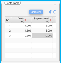
Depth Table
The depth table is used to define the depth of the beam.
Use the (+) and (-) buttons at the top of the table to add / delete rows to the Depth table.
[Organize] button can be used to sort the values in ascending order of 'Segment end' and to clean up empty entries in the table.
Table:
Double-click on the table cells to edit the content of the cells.
The table consists of three columns – 1) No., 2) Depth and 3) Segment End. The 'No.' column cannot be edited.
To enter the depth value, double click on the cell in this column and enter the value of depth for each segment. The depth values are restricted to the length of the beam.
Segment End Column – This defines the end value of each segment. For the first segment the beginning value is automatically assigned as zero. For all other segments the beginning value is automatically assigned the value corresponding to the end the previous segment. For the last segment it is mandatory to assign a value equal to the length of the beam.
Right click on the table to bring-up the context menu to insert / delete rows in the table, cut, copy, delete and paste contents into the table. It is also possible to copy the table from excel and paste the contents into this table. Ensure adequate number of empty rows are added to the table prior to pasting contents from an excel table.
The elevation view of the beam graphically shows the values entered in the table of depth segments:
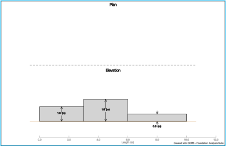
Beam Diagram
The beam diagram displays the plan and elevation view of the beam of the beam based on the length of the beam and values entered for the breadth and depth tables. The drawings are drawn to scale.
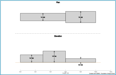
The corresponding values for the breadth and depth table are shown below. The beam has a length of 10m.
Beam Properties Tab
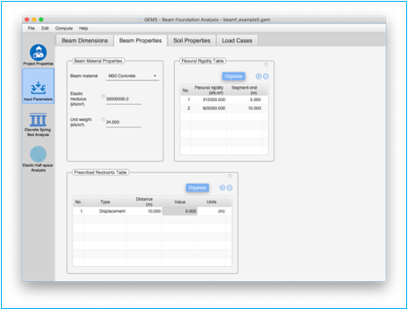
Beam material
Use the dropdown menu to select the material used for the beam. The elastic modulus of the beam along with the unit weight is updated based on the selection.
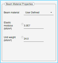
Table of Elastic modulus of beam
|
Beam Material |
Elastic Modulus |
|
|
(kN/m3) |
(kips/ft3) |
|
|
Concrete |
|
|
|
M20 |
3.0 * 107 |
6.26 * 105 |
|
M25 |
3.1 * 107 |
6.47 * 105 |
|
M30 |
3.3 * 107 |
6.68 * 105 |
|
M35 |
3.4 * 107 |
7.10 * 105 |
|
M40 |
3.5 * 107 |
7.31 * 105 |
|
M45 |
3.6 * 107 |
7.52 * 105 |
|
M50 |
3.7 * 107 |
7.73 * 105 |
|
Steel |
|
|
|
ASTMA36 |
2.0*108 |
4.173 * 106 |
Select the “User Defined” option to enter a user defined value for the elastic modulus of the beam.
Elastic modulus of beam
The elastic modulus of beam is shown here based on the material specified. If “User Defined” material is selected, the elastic modulus of the pile can be edited and entered here.
![]()
Unit weight of material
The unit weight of beam material of pile is shown here based on the material specified. If “User Defined” material is selected, the ‘unit weight of material’ can be edited and entered here.
![]()
Flexural Rigidity Table
The flexural rigidity table can be used to specify flexural rigidity for different sections beam. This is an optional parameter. The program will auto-calculate the values of flexural rigidities of the beam if the table is empty. Custom values can be specified for the beam by editing this table.
When the flexural rigidity table is empty, the program will calculate the flexural rigidity for the beam using the elasticity modulus of the beam, width and depth of the beam using the formula
![]()
To override the default values with custom values,
Use the (+) and (-) buttons at the top of the table to add / delete rows to the Flexural Rigidity Table.
[Organize] button can be used to sort the values in ascending order of 'Segment end' and to clean up empty entries in the table.
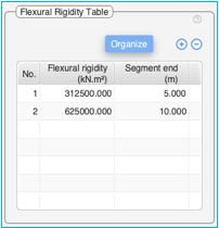
The table above shows the calculated flexural rigidities for a
M20 concrete beam (E = 3*107kN /m2) with following
dimensions
Length: 10m
Depth: 0.5m
Breadth:
|
Segment |
Breadth (m) |
|
0 – 5m |
1 |
|
5 – 10m |
2 |
Table:
Double-click on the table cells to edit the content of the cells.
The table consists of three columns – (1) No., (2) Flexural Rigidity and (3) Segment End. The 'No.' column cannot be edited.
Flexural Rigidity column – Double click on the cell in this column to enter the flexural rigidity for each segment.
Segment End Column – This defines the end value of each segment. For the last segment it is mandatory to assign a value equal to the beam length. For the first segment the beginning value is automatically assigned as zero. For all other segments the beginning value is automatically assigned the value corresponding to the end the previous segment. For the last segment it is mandatory to assign a value equal to the length of the beam.
Right click on the table to bring-up the context menu to insert / delete rows in the table, cut, copy, delete and paste contents into the table. It is also possible to copy the table from excel and paste the contents into this table. Ensure adequate number of empty rows are added to the table prior to pasting contents from an excel table.
Prescribed Restraints Table
The prescribed restraints table can be used to specify the values of various restraints on the beam. The below four restraints can be specified.
1. Displacement
2. Rotation
3. Vertical Spring
4. Rotational Spring
Use the (+) and (-) buttons at the top of the table to add / delete rows to the 'Prescribed Restraints Table'.
[Organize] button can be used to sort the values in ascending order of 'Distance' from the left of the beam and to clean up empty entries in the table.
A maximum of 10 values can be specified.
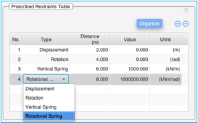
Table:
Double-click on the table cells to edit the content of the cells.
The table consists of five columns – 1) No., 2) Type, 3) Distance, 4) Value, 5) 'Units' column. The 'No.' column and 'Units' column cannot be edited.
Type Column: Click on the cell in the type column to bring-up a drop-down menu where the type of restraint can be selected. Select one of the four options – Displacement, Rotation, Vertical Spring, Rotational Spring.
Distance: Specify the distance from the start of the beam where the restraint is applied.
Value: Specify the value of the restraint applied at the point
Units: The unit value is populated based on the type of the restraint selected and the unit system selected in the project.
Right click on the table to bring-up the context menu to insert / delete rows in the table, cut, copy, delete and paste contents into the table. It is also possible to copy the table from excel and paste the contents into this table. Ensure adequate number of empty rows are added to the table prior to pasting contents from an excel table.
The above table specifies 4 different restraints specified on the beam. It also shows the dropdown menu for a fourth restraint.
The loading diagram below graphically represents the above prescribed restraints applied on the beam.
Soil Properties Tab
Specify the soil properties in the soil properties tab in the input parameters pane. Based on the analysis models selected, the soil properties tab will display the required parameters.
Soil Type – Select the soil type from the drop-down menu.
![]()
Parameters for 'Elastic Half-space analysis'
Elastic modulus of soil – Specify the elastic modulus of soil in the text box. The elastic modulus of soil is derived from penetration tests.
Poisson ratio of soil – Specify the Poisson ratio of soil in the text box.
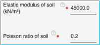
Un-drained elastic modulus coupled with a Poisson ratio value of 0.5 are used for analyzing immediate behaviour. On the other hand use of drained elastic modulus and drained Poisson ratio are used for analyzing long-term behavior.
Parameters for 'Discrete Spring Bed analysis'
Subgrade Modulus:
The modulus of subgrade reaction (k1) is usually specified for a plate of size of 1ft x 1ft. This modulus needs to be modified to account for the following before giving it as data to run the software:
i) Width of foundation
For clay soil
![]()
For sandy soil in kips - ft. units
![]()
in SI units
![]()
ii) Shape Correction:
For rectangle of size mB x B
![]()
iii) Depth correction:
This correction is applicable only for granular.
![]()
Taking all corrections in to account
For clay soils
![]()
For granular soils
![]()
The values of subgrade modulus entered as data should incorporate all corrections.
In the absence of field or laboratory data the following values proposed by Terzaghi may be used.
Values of modulus of subgrade reaction k1 for 1ft x 1ft square plates in kips/ft3
Granular Soil
|
Relative Density |
Low |
Medium |
Dense |
|
Dry or moist sand - limiting values |
40-120 |
120-600 |
600-2000 |
|
Proposed values for dry moist sand |
80 |
260 |
1000 |
|
Proposed values for submerged sand |
50 |
160 |
600 |
Values of modulus of subgrade reaction k1 for 1ft x 1ft square plates in kips/ft3
Clay Soil
|
Consistency |
Stiff |
Very stiff |
Hard |
|
Unconfined compressive strength(ksf) |
2-4 |
4-8 |
>8 |
|
Range of values |
100-200 |
200-400 |
>400 |
|
Proposed values for submerged sand |
150 |
300 |
600 |
Values of modulus of subgrade reaction k1 for 1ft x 1ft square plates in kN/m3
Granular soil
|
Relative Density |
Low |
Medium |
Dense |
|
Dry or moist sand - limiting values |
6300-18900 |
18850-94250 |
94250-157100 |
|
Proposed values for dry moist sand |
12570 |
40850 |
157100 |
|
Proposed values for submerged sand |
7850 |
25130 |
94250 |
Values of modulus of subgrade reaction k1 for 1ft x 1ft square plates in kN/m3
Clay soil
|
Consistency |
Stiff |
Very stiff |
Hard |
|
Unconfined compressive strength(kPa) |
50-100 |
200-400 |
>400 |
|
Range of values |
15710-31420 |
31420-62840 |
>62840 |
|
Proposed values for submerged sand |
23560 |
47120 |
94250 |
Subgrade modulus: This field should be used if “Discrete spring bed analysis model” and "Elastic half-space analysis model" are selected analysis in the project properties pane. The subgrade modulus is used for the evaluation of the discrete spring bed analysis model.
![]()
Subgrade modulus table: This table is visible when only the “Discrete spring bed" analysis model is selected in the project properties pane and is only applicable for the discrete spring bed analysis model.
Use the (+) and (-) buttons at the top of the table to add / delete rows to the 'Subgrade Modulus Table'.
[Organize] button can be used to sort the values in ascending order of 'Segment end' and to clean up empty entries in the table.
A minimum of 1 value and a maximum of 10 values can be specified over the length of the beam.
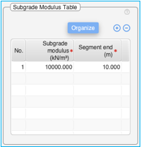
Table:
Double-click on the table cells to edit the content of the cells.
The table consists of three columns – 1) No., 2) Subgrade Modulus and 3) Segment end. The 'No.' column cannot be edited.
Subgrade Modulus column – Double click on the cell in this column to enter the subgrade modulus for each segment
Segment end Column – This defines the end of each segment measured from the beginning of the beam.
· There should be one segment which extends to the end of the beam.
· The segment end in no two rows should be same
Right click on the table to bring-up the context menu to insert / delete rows in the table, cut, copy, delete and paste contents into the table. It is also possible to copy the table from excel and paste the contents into this table. Ensure adequate number of empty rows are added to the table prior to pasting contents from an excel table.
Load Cases Tab
Enter the number of load cases in the project properties page.
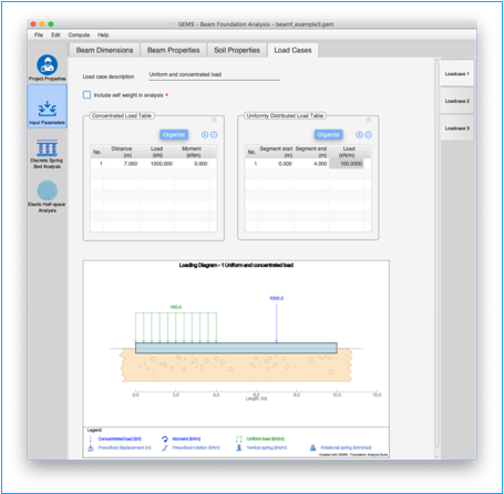
The ‘Load Cases’ tab is used to enter details of each load-case. Each load-case should be entered in a separate tab (on the righthand side). Each load case tab consists of load case description used for reference, a checkbox to indicate if the weight of the pile should be considered for analysis, axial load, lateral load and lateral moment. A loading diagram graphically represents the loads applied on the beam.
Load Case Description
Enter the description of the load case for your reference. This is an editable text field.
![]()
Include ‘self-weight’ in analysis
Select this checkbox if the weight of the beam is to be included in the analysis. The weight of the beam is calculated using the dimensions of the beam and the unit weight of material used.
![]()
The “self weight” assumes that the beam has a rectangular cross-section.
For beams with non-rectangular cross-section (example T Beams), do not use this option. One method of modeling this is to apply a uniform load across the beam equal to the cross-sectional weight of the beam.
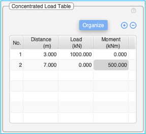
Concentrated load table
This table is used to specify the concentrated loads and moments applied on the beam.
Use the (+) and (-) buttons at the top of the table to add / delete rows to the Concentrated Load Table'.
[Organize] button can be used to sort the values in ascending order of 'Distance' from the left of the beam and to clean up empty entries in the table.
The table consists of 4 columns – 1) No., 2) Distance, 3) Load and 4) Moment columns. The 'No.' column cannot be edited. Double click on the cells to edit the contents of the cell.
Distance: Specify the distance from the start of the beam where the load is applied.
Load: Specify the load applied at the point
Moment: Specify the moment applied at the point
Right click on the table to bring-up the context menu to insert / delete rows in the table, cut, copy, delete and paste contents into the table. It is also possible to copy the table from excel and paste the contents into this table. Ensure adequate number of empty rows are added to the table prior to pasting contents from an excel table.
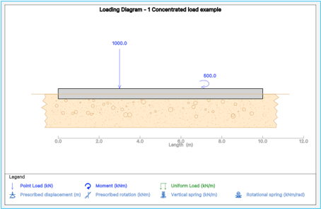
The example below shows a 10m long beam with 1000kN load applied at 3m from left and 500kN moment applied at 7m from left.
The loading diagram below graphically represents the above concentrated load and moment applied on the beam.
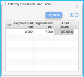
Uniformly distributed load table
This table is used to specify the uniform loads applied along the length of the beam.
Use the (+) and (-) buttons at the top of the table to add / delete rows to the Concentrated Load Table'.
[Organize] button can be used to sort the values in ascending order of 'Segment start column' and to clean up empty entries in the table.
The table consists of 4 columns – 1) No., 2) Segment start, 3) Segment end and 4) Load columns. The 'No.' column cannot be edited. Double click on the cells to edit the contents of the cell.
Segment start: Specify the distance from the start of the beam where the uniformly distributed load begins.
Segment end: Specify the distance from the start of the beam where the uniformly distributed load ends.
Right click on the table to bring-up the context menu to insert / delete rows in the table, cut, copy, delete and paste contents into the table. It is also possible to copy the table from excel and paste the contents into this table. Ensure adequate number of empty rows are added to the table prior to pasting contents from an excel table.
The uniformly distributed load is applied between segment start & segment end along the length of the beam.
Load: Specify the uniform load applied between the segment start & segment end. The load is specified in kN/m or kips/ft.
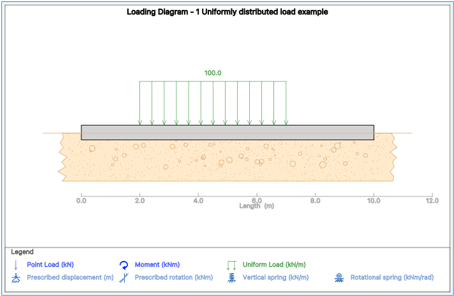
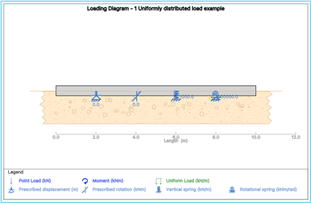
The example below shows a 10m long beam with 100kN/m load applied from a distance of 2m from the left end of the beam to a distance of 7m from the left end of the beam. Thus, the load spans a total distance of 5m from 2m to 5m.
The loading diagram below graphically represents the above uniformly distributed load applied on the beam.