Offshore Pile Foundation
As offshore energy exploration continues to expand, the importance of safe and reliable pile foundations for offshore platforms cannot be overstated. From jacket-type platforms to other complex offshore structures, pile foundations must be designed to withstand a variety of forces and moments under operational and severe storm conditions while meeting stringent safety and serviceability requirements
The main types of load to which the piles are subjected to are the axial compressive, tensile loads, lateral loads and moments.
The ‘Offshore Pile Foundation Analysis’ software of GEMS provides advanced and intuitive modules for all the above analyses.
There are three modules available
|
|
|
|


Key Features
|
· Axial pile capacity estimation · Analysis of the pile foundation under lateral and axial loads. · Generation of p-y, t-z and Q-z curves based on soil properties. · User defined p-y, t-z and Q-z curves. · Multiple load cases. · Pictorial representation of the pile and soil layers. · Loading diagrams for each load case. · One click computation and analysis for all load cases and modules. · Export of results to Microsoft Word, Excel & PDF · Supported on Windows, Mac and Cloud · Data can be input in either SI units or ‘Commonly used American units’ (kips for force and foot for length). · Handy tool for resolving forces. |
· Multiple axial, lateral loads and lateral moments can be specified along the length of the pile at various depths (up to 20 including pile head) for each load case. · Distributed lateral load (triangular, uniform, or trapezoidal) can be given. · Static and cyclic loadings can be incorporated for lateral analysis. · Self-weight of pile may be included if required. · Local scour consideration. · Pile thickness can be varied along the length of the pile. · Specify cross-sectional axial rigidity (AE) parameters of segments · Facility of prescribing lateral displacement, rotation & rotational spring at the pile head. · Consideration of group effect by user prescribed p-multiplier, y-multiplier & z-multiplier. · Graded mesh for lateral pile analysis along the pile length for better accuracy |
Modules
The ‘Offshore Pile Foundation Analysis’ suite of GEMS provides advanced and intuitive program modules for:
Pile Capacity Estimation
The ultimate axial capacity under compressive or tensile load is computed based on the soil layer properties. The software gives the pile capacity at various depths of soil and also breaks it down to its contributing factors viz. shaft friction and base capacity. Different codes and practices can be used in the calculation of pile capacity.
|
Soft Clay |
Stiff Clay |
Sand |
Weak Rock |
Hard Rock |
|
· API-2011 · API-2000 · API RP2A-1986 & TOMLINSON α = 0.7 |
· API-2011 · API-2000 · API RP2A-1986 & TOMLINSON α = 0.7 |
· API-2011 · API-2000 |
· Elastic (continuum) Bi-linear t-z q-z springs |
· Elastic (continuum) Bi-linear t-z q-z springs |
In both clay and sand layers fully plugged condition at the base is assumed in computing the total base capacity. A distance of 3D is used for developing full base resistance in strong layers. At the interface between soil layers the base capacity is made equal to the minimum of the two layers and increased to full value at an embedment of 3D.
A cushion depth of 3D is adopted whenever a weak layer underlies a strong layer. A safe distance of from pile tip of 3D is adopted to preclude punch through underlying weak layers.
For rock layers an approach based on unconfined strength is adopted.
The total shaft friction at given depth z is computed as ![]() up
to that depth. The depth ranges from mudline to sum of all the layer
thicknesses.
up
to that depth. The depth ranges from mudline to sum of all the layer
thicknesses.
The base capacity is calculated on the basis of fully plugged condition using gross area at the base.
Axially Loaded Pile Analysis
This module has two independent sub modules:
Generation of t-z and Q-z curves
Development of a set of t-z curves along the shaft length and Q-z curve at the pile base for compressive loading. Multiple t-z curves are generated for each soil layer. The below methods are available for generation of the t-z for each layer and Q-z curves at the pile tip.
|
Soft Clay |
Stiff Clay |
Sand |
Weak Rock |
Hard Rock |
|
· API-2011 · API-2000 · API RP2A-1986 & TOMLINSON α = 0.7 |
· API-2011 · API-2000 · API RP2A-1986 & TOMLINSON α = 0.7 |
· API-2011 · API-2000 |
· Elastic (continuum) Bi-linear t-z q-z springs |
· Elastic (continuum) Bi-linear t-z q-z springs |
API based methods, also account for reduction in post peak adhesion in clay layers through a factor R.
Axial pile deformation analysis
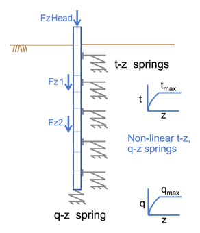
Interaction between pile and soil is implemented by finite element modelling of pile as an elastic structural member of variable axial rigidity, soil support along pile shaft by a set of t-z springs and the base support is a Q-z spring. Both t-z and Q-z springs represented by curves, model the non-linear nature of soil support. Either user defined t-z, Q-z data or curves generated in module based on soil properties can be used. The analysis uses an Iterative approach to achieve convergence.

Modelling of soil support using t-z & q-z springs
The following loading may be given and used for the analysis
a) Axial loads at various depths along the length of the pile (up to 20 including load at pile head).
b) Self-weight of the pile
The analysis provides settlement of the pile head under a given load on the pile, variation of axial load along the pile length, and the load carried by the pile base. Different loads applied on the pile head and the corresponding head settlements provide the load settlement curve.
Laterally Loaded Pile Analysis
This module has two independent sub modules.
Generation of p-y curves.
In this module p-y curves are generated for the soil layers based on their properties. Multiple p-y curves are generated for each layer. The below methods are available for generation of p-y curves based on soil type.
|
Soft Clay |
Stiff Clay |
Sand |
Weak Rock |
Hard Rock |
|
· API-2011 |
· API-2011 · REESE |
· API-2011 · Hybrid model for liquified sand (Based on friction angle) |
· REESE |
· Turner (2006) |
Lateral pile deflection analysis.
Analysis of a pile subjected to lateral load and moment is carried out in this module. Finite element based approach is adopted to model the pile and the soil support. The pile is modelled as an elastic member divided in to a number of bending elements. The soil support stiffness and strength is modelled by a series of non-linear discrete springs distributed continuously along the pile length based on the p-y curves.
Modelling of soil support using p-y springs
The following loading may be given and used for the analysis
a) Lateral loads, lateral moments and axial loads can be specified along the length of the pile at various depths (up to 20 including pile head) for each load case. The axial load applied at the pile head will be considered for taking the beam-column effect into account.
b) Distributed lateral load for a section along the pile length. Loading can be triangular, uniform, or trapezoidal.
The following boundary conditions may be given at the pile head
a) Prescribed lateral displacement
b) Prescribed rotation
c) Prescribed rotational stiffness.
For pile having free head condition both lateral load and moment can be prescribed at the pile head. The method can consider the effect of axial loading at the pile head due to beam column action in lateral pile analysis. The pile head can project above the ground.
Data on the p-y curves may be specified by the user or data generated in the module based on the soil properties could be used.
The finite element discretization not only takes in to account the specified pile make-up but is also optimized for better accuracy by adopting a graded mesh along the pile length. An iterative procedure based on secant modulus approach is used for convergence.